 LoRa technology is emerging as an innovative wireless communications solution for organizations across industries. By communicating data over a long range using very little power, these LoRa devices help connect our digital world. With an ever-increasing list of LoRa-driven use cases in smart agriculture, smart cities, smart homes and buildings, industrial IoT (IIoT), and beyond, LoRa range testing experiments are crucial for validating, optimizing and understanding the real-world performance of these connected devices.
Seeking valuable insights to improve design decisions, optimize network deployment and set realistic performance expectations, we recently completed a LoRa range testing experiment — and are excited to share our learnings and best practices!
Contents
Understanding LoRa vs. LoRaWAN
LoRa and LoRaWAN are not synonymous terms despite often being used interchangeably. The network on which all LoRa devices operate, LoRaWAN defines a device’s communication protocol and system architecture, while LoRa is a physical proprietary radio communication technique based on spread spectrum modulation techniques. LoRa provides a wireless communication link between individual LoRa devices (or nodes) and a LoRa gateway.
LoRa on its own is needed for a few reasons:
- Latency: LoRaWAN has higher latency because it is a protocol on top of LoRa and a reliable carrier (includes acknowledgment packets, etc.).
- Synchronous Communication: If the application demands communications and responses fall in a certain command/response structure and below a fixed time delta.
LoRa devices cannot send and receive data simultaneously. Therefore, careful management is necessary to enable sending without acknowledgment packets by ensuring each end is in the proper state before sending or expecting a packet. LoRa and LoRaWAN provide the framework for managing large-scale IoT networks and the technology enabling long-range, low-power connectivity between individual devices and gateways within those networks.
For more information, check out our blog posts on how to set up and work with a LoRa device and setting up a LoRa gateway to view IoT device data.
LoRa Range Testing
To gain practical insights into the range capabilities of LoRa devices, we designed our experiment to mimic practical, real-world scenarios with basic antennas, a basic dev board and a real-world environment — not a hot air balloon and the top of a mountain.
Antenna and Development Board Used
We utilized the weatherproof Omni-Directional Antenna Fiberglass 9dBi 920 ~ 980MHz antenna, commonly used in wireless communication systems. Designed to radiate and receive electromagnetic signals in a 360-degree pattern, the antennas provide coverage in all directions. The 9dBi gain signifies that the antennas deliver a higher signal concentration and amplification level in the horizontal plane, resulting in an extended range and improved signal strength. In our experiment, the antennas were positioned 10 feet off the ground to mimic a realistic deployment scenario while minimizing obstructions that can block or attenuate the signal, reducing the impact of ground reflections and maximizing the coverage area to evaluate the signal’s reach and performance over the testing area.
We also used a NUCLEO-WL55JC STM32WL Nucleo-64 board from our partner STMicroelectronics to facilitate the evaluation and development of wireless applications. This board, built around the STM32WL microcontroller, balances processing capabilities and low-power operation, making it suitable for IoT applications requiring wide coverage and low power consumption.
Configuration Settings
Our configuration settings included a spreading factor (SF) of 6 to 12 and a coding rate (CR) of 4_5 to 4_8. These settings allowed us to evaluate the impact of different combinations on factors such as latency, reliability and range.
Spreading Factor (SF)
The SF determines the rate at which data is spread over a given bandwidth in LoRa modulation. A lower SF offers lower latency (faster transmissions) but less range because higher spreading factors are more resilient to lower radio frequency receive powers. A higher SF, however, results in a slower data rate but provides increased robustness against noise and interference.
Coding Rate (CR)
The CR determines bit-level redundancy, with 4_5 being one extra bit per four bits of data and 4_8 being four extra bits per four bits of data. A higher CR means higher error resilience of the transmitted signal but lower speed due to essentially multiplying the number of bits in a packet by two, resulting in longer transmission times and increased latency.
In LoRa range testing, finding the optimal spreading factor and coding rate combination is essential to balance latency and range.
Testing Locations
 Testing in different environments is crucial for accurately assessing the range capabilities of LoRa devices. From signal propagation variations and interference to specific use case considerations and performance optimization, conducting range testing in diverse environments empowers a comprehensive understanding of deployment strategies, antenna placement and optimization measures.
Our experiment’s primary testing area covered a 2-mile area over McIntosh Lake and a dirt intersection near the lake in Longmont, Colorado. Testing over the lake offered an unobstructed line-of-sight environment, with minimal physical barriers attenuating or blocking the LoRa signals. While LoRa range testing over a lake might provide beneficial conditions for LoRa signals, considering how reflection, refraction, signal interference, the Fresnel Zone (more below) and multipath propagation can impact signal quality is vital during the range testing analysis.
Fresnel Zone Considerations

Source: Wikipedia
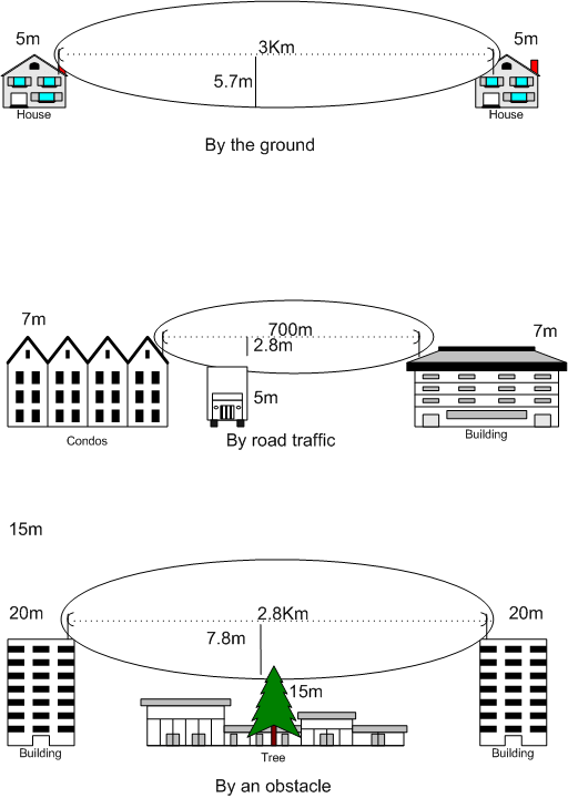
An elliptical region around the direct line-of-sight path between a transmitter and a receiver, the Fresnel zone plays an important role in radio transmission, accounting for the fact that signals spread out in an elliptical pattern. Obstacles within this zone can cause signal blockage, reflection or diffraction, degrading the signal and reducing the device’s range.
In our case, the Fresnel zone included water from the lake, ground and trees, each potentially affecting signal propagation differently.
Evaluation of Different Packet Sizes
We tested different packet sizes to assess their impact on the performance and range capabilities of our LoRa devices. Smaller packet sizes generally result in shorter transmission times, leading to lower latency, whereas larger packets — which consume more bandwidth — require more robust signal strength to be successfully received at longer distances.
We initiated the packet transmission from the sender node to the receiver node, recorded a timestamp when the packet left one node and entered the network and did the same thing when the packet reached the receiving end to calculate one-directional latency. Leveraging that calculation, we computed the round-trip latency using our application’s requirements by sending, receiving and timestamping the details of a response packet’s journey to assess the LoRa device’s data transmission responsiveness and timeliness.
By evaluating a range of packet sizes, we aimed to optimize for factors like latency, error rates, network efficiency and range, ultimately determining the ideal packet size that balances these considerations — between 5 and 20 bytes per packet — based on our specific application requirements.
Challenges and Insights from LoRa Range Testing
One significant challenge in setting up our experiment was finding the right location with a clear line-of-sight and no obstructions over an extended distance. Geographic obstructions and land-use concerns posed limitations in selecting suitable testing areas.
Another challenge involved calculating our link budget and signal-to-noise ratio (SNR). Knowledge of the link budget, which represents the overall system gain or loss throughout the communication path, and the SNR, which measures the desired signal strength relative to the background noise level, is crucial for assessing the performance and range capabilities of LoRa devices.
Calculating the gains and losses in the link budget helps estimate the theoretical signal strength. Sum them together (gains are positive, losses are negative) for a theoretical result signal strength. Some are provided (antenna gain, transmit power), but others require calculation. For example, feed line loss, which measures the cable loss between the antenna and the board, is easy to calculate using a spectrum analyzer, and free space loss is calculated based on distance and frequency.
LoRa Insights and Best Practices
Through our testing experience, we gained valuable insights and best practices for optimizing LoRa device performance and range:
- Selecting the appropriate spreading factor and coding rate combination is essential based on specific application requirements and performance goals. Higher spreading factors and coding rates offer increased robustness against noise and interference but result in slower data rates and higher latency.
- Optimizing packet sizes is crucial for balancing factors like latency, error rates and range. While smaller packets generally offer lower latency, larger packets may require more robust signal strength for successful transmission over longer distances.
- Considering the Fresnel zone and its impact on signal propagation is vital when planning antenna placement and network deployment. Obstacles within the Fresnel zone can degrade the signal, reducing the device’s range.
- Mitigating signal interference, multipath propagation and other potential issues through proper planning and deployment strategies is crucial for achieving optimal performance.
Connect with Cardinal Peak for Comprehensive LoRa Solutions
At Cardinal Peak, we understand the critical considerations when deploying LoRa devices. Our expertise with LoRa technology, accurate range assessments and comprehensive testing capabilities help mitigate risks and accelerate development.
With our extensive experience and expertise across industries, we can help bring your LoRa device ideas to life. Cardinal Peak is here to assist if you’re looking to develop your next connected device! Our team of experts looks forward to discussing your project requirements — connect with us today!
Additional Resources
Check out our other blog posts on LoRa:
- How To Set Up And Work With A LoRa Device
- Everything You Need To Know About LoRa & How To Set Up A LoRa Gateway To View IoT Device Data
- LoRa And Semtech And Sigfox, Oh My
