One of the most critical elements of wireless communication is not a single component but a system consisting of analog and digital components? Whether you’re streaming your favorite movie, making a voice call or connecting to a Wi-Fi network, a phase-locked loop — or PLL — is the system enabling these technologies to work seamlessly.
In the first edition of this blog series, we’ll explore the inner workings of phase-locked loop circuits and their vital role in wireless applications.
Contents
What is a Phase-Locked Loop?
A PLL is an electronic circuit that synchronizes the phase and frequency of an oscillator signal with a reference signal. As part of the phase detector, you can adjust or move the phase relative to the input reference, by using delay lines, multiplying clocks, etc. Also, viewers of this input file can see comments and suggestions.
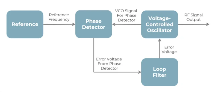
Essentially a feedback control system, PLLs comprise three main components:
- A phase detector compares the phases of the input reference signal and the feedback signal from the voltage-controlled oscillator to generate an error signal proportional to the phase difference between the two signals.
- A low-pass filter smooths out the error signal from the phase detector, removing high-frequency noise and ensuring a stable control signal.
- A voltage-controlled oscillator (VCO) that generates an output signal with a frequency proportional to the input control voltage from the low-pass filter.
Basic Phase-Locked Loop Diagram

Widely used in wireless or radio frequency (RF) applications, a phase-locked loop design creates a “negative feedback” loop to continually adjust the VCO’s output frequency, ensuring it remains synchronized with the reference signal as the control voltage changes.
How Do Phase-Locked Loops Work?
A PLL’s operation revolves around the feedback mechanism. The phase detector continuously monitors the phase difference between the reference signal and the VCO output. Any signal discrepancy — a phase difference — generates an error signal that adjusts the VCO, synchronizing the output signal with the reference signal.
References are typically where the high accuracy and stability is achieved and normally based on TCXO/OCXO clock oscillators for low phase noise. Feedback division can utilize many different flavors (including a simple N frequency divider, dual-modulus prescaler, etc.) to achieve the desired output frequencies.
By reducing phase errors between output and input frequencies, this process of continual adjustment ensures that the PLL maintains phase synchronization. In addition to synchronizing the output and input frequencies, a PLL also helps generate the appropriate control voltage, achieving both frequency and phase lock in a circuit.
With two signals operating at the same exact frequency, PLLs are useful building blocks, particularly for wireless and RF applications.
Typical Phase-Locked Loop Applications
Locked PLL circuits are widely used for synchronization in Wi-Fi routers, walkie-talkie radios, televisions, GPS systems, and mobile phones. They also enable the development of several other PLL applications.
- FM/AM and FSK demodulation: One primary phase-locked loop application is demodulating high-quality audio from FM and AM signals (e.g., broadcast radio). PLLs can also transmit binary data by shifting a carrier frequency between two preset frequencies.
- Signal recovery: Locked PLL circuits provide a clean signal and remember the signal frequency if there is a short interruption or the signal is lost in noise. This application is particularly useful when using pulsed transmissions.
- Indirect frequency synthesis: By placing a digital divider or mixer into the phase-locked loop, synthesizing signals on new frequencies is possible. PLLs enable the generation of accurate carrier frequencies in Wi-Fi routers, for example, ensuring robust and reliable wireless communication.
- Timing distribution: PLLs distribute precisely timed clock pulses in digital logic circuits and systems, for example, within microprocessors.
- Digital signal processing of video: Phase-locked loops synchronize the phase and frequency to the input analog video signal for sampling and digital signal processing.
- Clock recovery and generation: Some data streams, especially high-speed serial data streams, require receivers to generate a clock from an approximate frequency reference and use a PLL to phase-align it. Plus, many processors in electronic products operate well above the practical frequencies of crystal oscillators. Typically, the clocks supplied to these processors are generated by PLLs, which multiply a lower-frequency reference clock up to the processor’s operating frequency.
PLLs ensure precise frequency control in radio communication, and modern TVs utilize PLLs for channel tuning and signal synchronization. Finally, PLLs are essential in mobile phones for frequency synthesis in the transceiver circuits, enabling stable communication and signal integrity.
PLLs can be used across various frequencies, ensuring that devices operate at precise frequencies and filtering out high-frequency noise. These capabilities make them versatile components in various modern electronic applications.
Final Phase-Locked Loop Thoughts
Understanding the basic principles and applications of PLLs provides valuable insight into the technological backbone of modern communication systems. In the next part of this blog series, we’ll delve deeper into the engineering principles behind PLLs and explore their specific implementation in innovative products.
- Part two of this series explores phase-locked loops in automotive audio systems. We’ll dive deeper into the relationship between PLLs and the generalized precision time protocol (gPTP), revealing how these components work together to maintain perfect audio synchronization. Part two will also uncover the complexities of buffer management, the challenges of implementing timing protocols and the crucial role that experienced software teams play in bringing these systems to life, delivering exceptional audio experiences and pushing the boundaries of wireless technology.
- Part three of this series navigates embedded memory security challenges in connected car systems. If you’ve ever wondered about the security implications of peripheral devices in modern automotive systems, this post explores the risks, the debate between hardware and software teams and proven strategies for protecting these critical components.
With our extensive experience and expertise across industries, we can help bring your wireless solutions to life. Our team of experts looks forward to discussing your project requirements — connect with us today!
