One of our clients is heavily involved in 3D video and has been for several years. However, several are just now starting to think about it because of the uptick of interest in the consumer electronics world. Enough questions have been posed to us recently that it seemed worthwhile to me to pull together a few basic facts regarding 3D stereo-pair imaging and stereo disparity.
First, we need a simple model of a lens. Consider the diagram below:
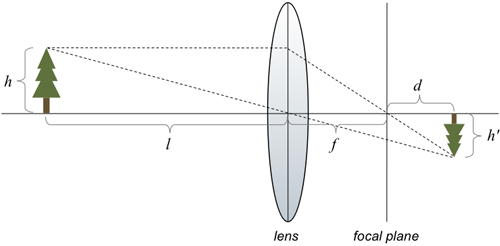
In this picture, the long horizontal line that passes through the center of the lens is called the lens axis. The lens has the property that rays that pass through the center of the lens are undeviated. Therefore, the ray from the top of the tree, at a distance l to the left of the lens, passes straight through the center of the lens. (The tree has a height of h.) The lens also has the property that rays that arrive perpendicular to the lens are refracted to pass through the focal point of the lens. The focal point lies on the lens axis and is a distance f from the center of the lens. The intersection of these two rays shows where the image of the tree will be formed. You can see that the image of the tree is upside down, and has a new height h’. The image is formed a distance d to the right of the focal point.
By using similar triangles we see first that
\dfrac{h}{f}=\dfrac{h^\prime}{d}
Using a different pair of similar triangles we also see that
\dfrac{h}{l}=\dfrac{h^\prime}{f+d}
Solving the first equation above for h’. substituting the result into the second equation and simplifying, we derive the following relationship:
\dfrac{1}{f+d}+\dfrac{1}{l}=\dfrac{1}{f}
This is the fundamental equation of a simple lens. It shows that as the object gets further and further from the lens, i.e. as l increases, the distance of the image of the object from the focal plane decreases, i.e., d gets smaller. We can assume that the camera’s image sensor is located at a distance f from the lens, is perpendicular to the lens axis, and that all objects more than a certain distance away from the lens will be in focus. In other words, the image of all sufficiently distant objects will appear on the focal plane where the image sensor is located.
In the case of 3D video, two cameras are used to acquire a sequence of stereo-pair images, one from the left camera and one from the right. Different stereo geometries are possible, but the most common one is to place the two cameras horizontally apart from each other by a distance i, and to keep their focal planes coplanar. The diagram below illustrates this configuration:
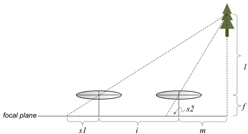
The horizontal line at the bottom is the focal plane; it is clear from the diagram that the focal planes are coplanar. The lenses are a distance f from the focal plane and are separated by a distance of i from each other. We assume that a small object (or a point on a larger object) is located a distance l from the lens plane and a distance m to the right of the axis of the right lens. We want to know where the image of that object appears in the left and the right camera. In particular, we want to know if we overlaid the left image on top of the right image, how far apart would the images appear? Mathematically, we want to know the disparity, which we define to be
\rho = s1-s2
where s1 and s2 are the distances from the image point to the intersection of the lens axis with the focal plane for the left and the right cameras respectively. Note that we are assuming that the object being imaged is far enough away that its image forms on the focal plane.
Using our favorite trick of similar triangles we have the following two equations:
\dfrac{f}{s1}=\dfrac{l+f}{s1+i+m}
and
\dfrac{f}{s2}=\dfrac{l+f}{m+s2}
Solving the first equation for s1, the second equation for s2, taking the difference and simplifying yields
\rho=\dfrac{fi}{l}
Although this expression was derived for an object to the right of the axis of the right camera, it is easy to show in a similar manner that it is also true for an object between the axes of the two cameras as well as for an object to the left of the axis of the left camera.
So what does this equation tell us? First, it says that for this particular camera geometry, the disparity is only a function of the separation between the two cameras, i, and the distance of the object from the lens plane, l. Second, the equation tells us that the disparity increases as we increase the separation between the cameras. Finally, it tells us that the disparity decreases as the object gets further away from the cameras, approaching zero for objects an infinite distance away. (You can see this when you watch 3D content without wearing the special 3D glasses: The “distant” objects can be seen by the naked eye, whereas the near objects appear blurry to the naked eye because the value of ρ is greater.)
It should be clear from this equation that if a stereo pair is available, and corresponding points can be found in the left and right pictures, that the disparity between those points can be measured, and the distance to the point can be computed.
Mike Perkins, Ph.D., is a managing partner of Cardinal Peak and an expert in algorithm development for video and signal processing applications.